Our Store
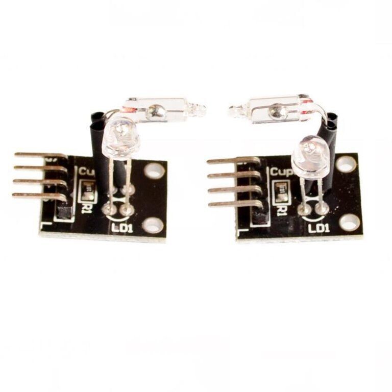
Light Module Light Cup Board KY-027
Light Module Light Cup Board KY-027 PWM Output Arduino DIY project
Control LED Status For Arduino DIY Project Working Voltage 5V Output: Digital Voltage Output (0/1) PWM Output Material: PCB Colour: Black Dimensions: 0.91 x 0.79 x 0.59 Inch / 2.3 x 2 x 1.5 CM PACKAGE INCLUDES: Light Module Light Cup Board KY-027 PWM Output Arduino DIY project Arduino Sketch Below:
int LedPinA = 5;
int LedPinB = 6;
int ButtonPinA = 7;
int ButtonPinB = 4;
int buttonStateA = 0;
int buttonStateB = 0;
int brightness = 0;
void setup()
{
pinMode(LedPinA, OUTPUT);
pinMode(LedPinB, OUTPUT);
pinMode(ButtonPinA, INPUT);
pinMode(ButtonPinB, INPUT);
}
void loop()
{
buttonStateA = digitalRead(ButtonPinA);
if (buttonStateA == HIGH && brightness != 255)
{
brightness ++;
}
buttonStateB = digitalRead(ButtonPinB);
if (buttonStateB == HIGH && brightness != 0)
{
brightness --;
}
analogWrite(LedPinA, brightness); // A will turn off gradually
analogWrite(LedPinB, 255 - brightness); // B will turn on gradually
delay(25);
}
Terminals
G = Ground
+ = +5V
S = Signal
L = LED
Another Code example Arduinoint Led = 13 ;// Declaration of the LED-output pin
int Sensor = 10; // Declaration of the sensor input pin
int val; // Temporary variable
void setup ()
{
pinMode (Led, OUTPUT) ; // Initialization output pin
pinMode (Sensor, INPUT) ; // Initialization sensor pin
digitalWrite(Sensor, HIGH); // Activating of the internal pull-up resistor
}
void loop ()
{
val = digitalRead (Sensor) ; // The current signal from the sensor will be read
if (val == HIGH) // If a signal will be detected, the LED will light up.
{
digitalWrite (Led, LOW);
}
else
{
digitalWrite (Led, HIGH);
}
}
Connections Arduino:
LED + = [Pin 13]
LED - = [Pin GND]
Sensor signal = [Pin 10]
Sensor +V = [Pin 5V]
Sensor - = [Pin GND]
Code example Raspberry Pi
# Needed modules will be imported and configured.
import RPi.GPIO as GPIO
import time
GPIO.setmode(GPIO.BCM)
# Declaration of the LED and sensor pins
LED_PIN = 24
Sensor_PIN = 23
GPIO.setup(Sensor_PIN, GPIO.IN)
GPIO.setup(LED_PIN, GPIO.OUT)
print "Sensor-test [press ctrl+c to end the test]"
# This output function will be started at signal detection
def ausgabeFunktion(null):
GPIO.output(LED_PIN, True)
# This output function will be started at signal detection
GPIO.add_event_detect(Sensor_PIN, GPIO.FALLING, callback=ausgabeFunktion, bouncetime=10)
# main program loop
try:
while True:
time.sleep(1)
# output will be reseted if the switch turn back to the default position.
if GPIO.input(Sensor_PIN):
GPIO.output(LED_PIN,False)
# Scavenging work after the program has ended
except KeyboardInterrupt:
GPIO.cleanup()
Connections Raspberry Pi:
LED = GPIO24 [Pin 18]
Signal = GPIO23 [Pin 16]
+V = 3,3V [Pin 1]
GND = GND [Pin 6]


